Sponsored

Adding Ambient Lighting onto Non-AL Mustang

slowboy2.3

Active Member
Joined
Jul 15, 2025
Threads
4
Messages
30
Reaction score
12
Location
Texas
Vehicle(s)
2025 Mustang Ecoboost
This is gonna be a long read, just an fyi...

For reference purposes, I have a late production Mustang (no BCMB), so I didn't have the option of just enabling the ambient lighting zones. I didn't see any different BCM models when researching this mod, so I generally assumed that the only differences between the trim levels were the programming of the modules.

So far, I've made the wiring harness for the footwell lighting and have wired it directly into the BCM (in hindsight, I should've wired it into the interior wiring connector, then to the footwell lights, but that's a later me problem). The problem now is getting the lights to work. I am not getting any DTCs or errors when changing the ambient lights through myColor, so I don't believe it's an APIM configuration or GWM communications error (unless the GWM is ignoring the messages entirely, which I'm not ruling out), but since I don't have access to FDRS, it's a long shot as to what is causing the behavior.

I haven't made any changes to the BCMs AsBuilt since it's basically identical to a GT Premium's AsBuilt in regards to lighting, +/- some unknown options. I made the AL changes in the APIM, and I believe that was the only module that needed changes for AL.

Wiring this was nothing short of maddening, as I couldn't find any resources for the late production BCM wiring. So, off to buy the FDRS subscription I went. I ended up finding the correct diagrams and connector pinouts, so I purchased the necessary components to make the harness, and it has been completed. Ford did split the AL zones' wiring across two connectors (a byproduct of condensing the BCMB, I assume), and the only modification to the harness I made was to add the green pin. The ground pin is shared, and the red/blue wires were already present on the other connector.

I didn't wire for Zone 3, since the zone is not going to be used for the following purposes. I wired exclusively for Zone 1. I did test continuity on the harness before I plugged everything back in, and I did confirm the lights worked by testing them on another Mustang. No shorts or fuse pops were heard when everything was put back together, so I think I had a good start. After that, I ran out of luck, and we are here now.

The goal now is to see whether or not this is a BCM programming issue that is causing the lights not to work. I am taking the car to the dealership soon for an oil change, and I will ask if they can do some magic to get the ambient lights working. I'm not getting my hopes up since this is a very sketchy mod in terms of execution, and I won't be surprised if they refuse to look at it.

I'll post an update once I get something working. For now, it isn't causing an issue remaining plugged in, so I'll leave it alone until then.

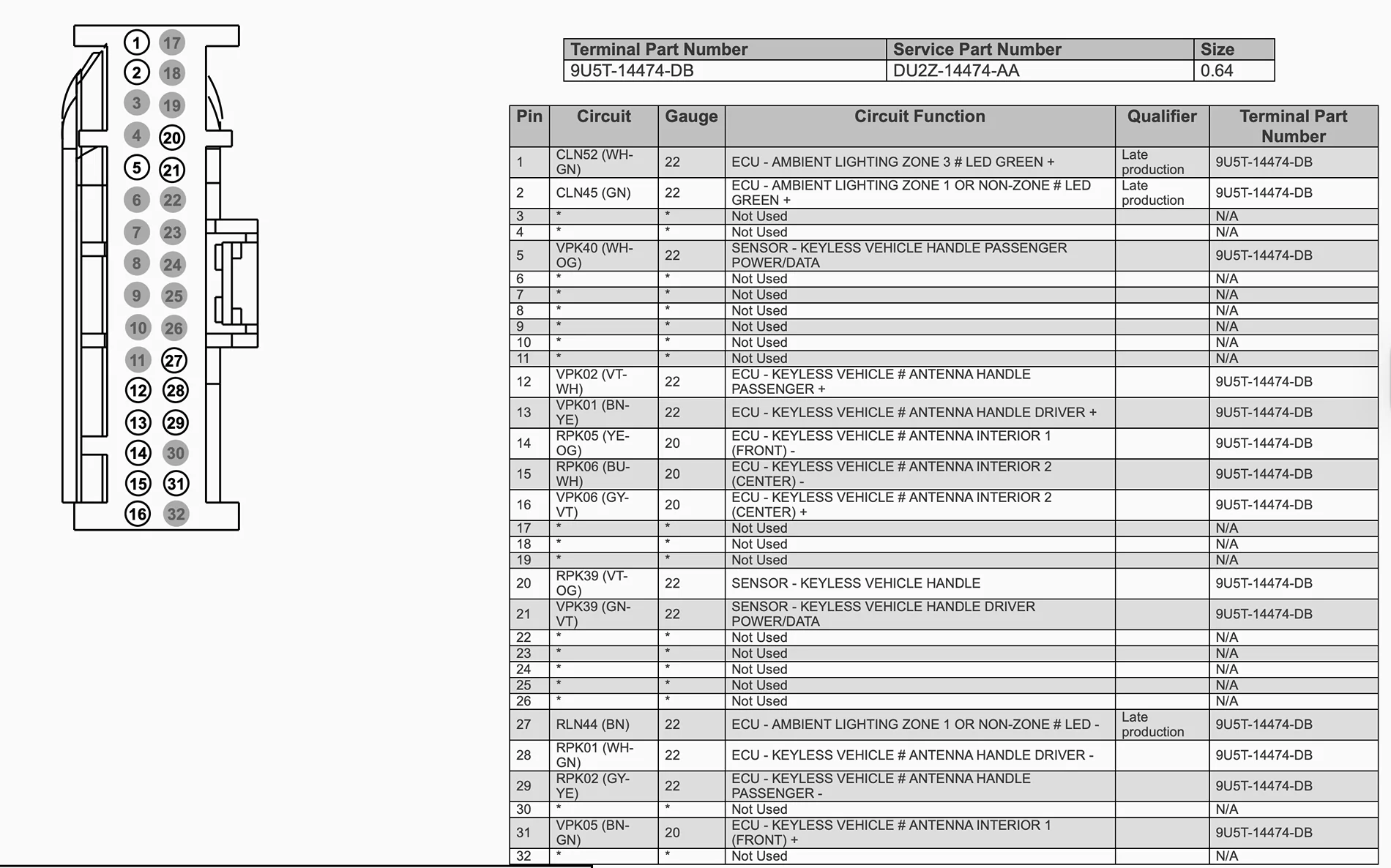
Below is Connector C2280D (J4 on the BCM). Pin 2 is AL Zone 1's Green, and Pin 27 is AL Zone 1 Ground (might be Zone 3's ground as well, as it did not specify that on the connector diagram). Pin 27, or wire RLN44, is shared with a few other circuits, so I caution against anything drastic with that wire.

Screenshot 2025-11-09 at 10.42.11 PM.webp


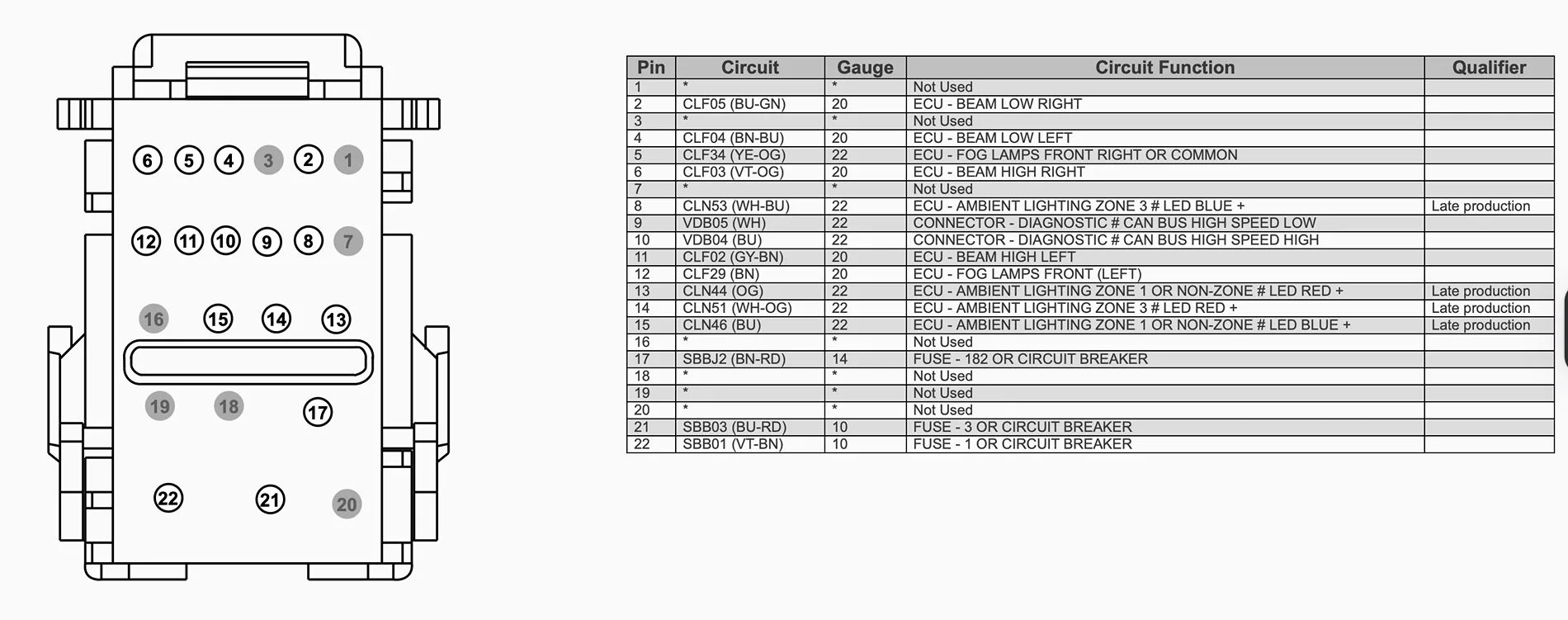
Below is Connector C2280G (J7 on the BCM). Pin 13 is AL Zone 1's Red, and Pin 15 is AL Zone 1's Blue. There is no ground pin for AL on this connector. This connector leads to the HCM, so definitely don't fudge with this one too much unless you want to do just that.

Screenshot 2025-11-09 at 10.41.22 PM.webp


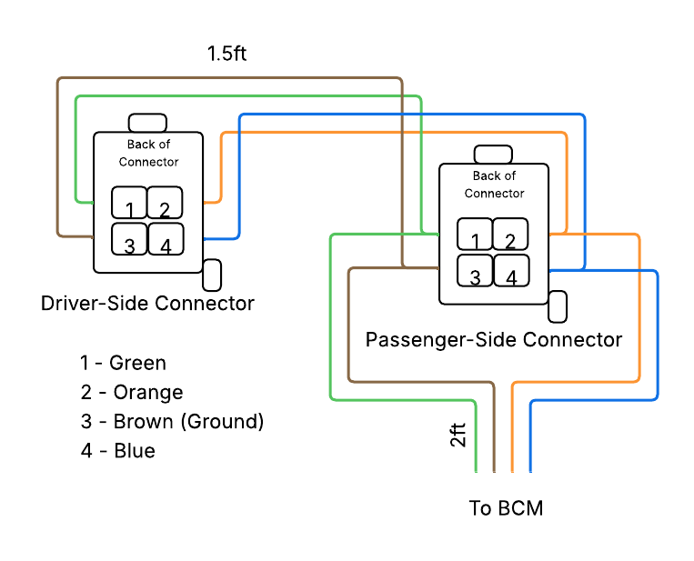
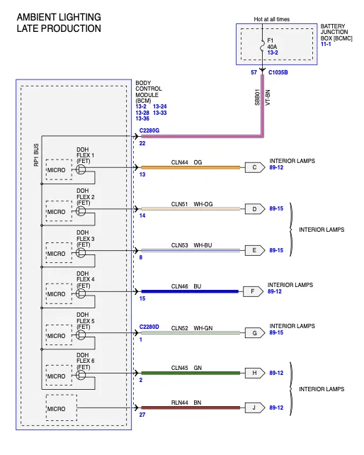
Onto the pièce de résistance, the wiring diagram for the wire itself... Pretty self explanatory... Red to red, green to green, and blue to blue. Ground is just ground. Zone 3's wiring is also in this picture, in case you want to add AL door sills. Zone 1 leads to a splice with the door lights, goes back to the interior lights connector, and then to the footwell lights.

Screenshot 2025-11-09 at 10.38.03 PM.webp


tl;dr, ambient lighting no work, no clue why it wouldn't work, taking to dealer to hopefully have looked at but also looking for community suggestions/support
Sponsored

 
OP
OP
slowboy2.3

slowboy2.3

Active Member
Joined
Jul 15, 2025
Threads
4
Messages
30
Reaction score
12
Location
Texas
Vehicle(s)
2025 Mustang Ecoboost
Diving back into this, there are two lines in the BCM configuration, 726-37-01 and 726-37-02, that stand out because they include the flexible circuits. It is disabled in my Mustang's BCM, but enabled in every late production Mustang that has AL optioned from the factory.

Additionally, comparing this to the AL wiring diagram reveals that there are six individual microcontrollers, each with its own flexible circuit notation. I want to assume that these flexible circuits are what provide power to the AL, but I cannot confirm it since options 7 and 4 are not on the FORSCAN spreadsheet for those circuits.

Here are the lines from my Mustang and the lines from a Mustang optioned with AL.
x - Flexible CircuitsMy MustangMustang with AL
726-37-01
*********x**
01001E1E00A2
01001E1E07A9
726-37-02
*x*x*x*x*x**
000000000066
07040404047D
 

MRI204

Well-Known Member
Joined
Dec 11, 2019
Threads
0
Messages
100
Reaction score
86
Location
Italy
Website
www.grena.com
Vehicle(s)
MY2006 GT Roushcharged MY2020 Bullitt L2061 (sold) Q767 Dark Horse R8339
If it helps, the instructions explain the wiring step-by-step...

I'm having the same problem.
I sent my Dark Horse to Germany to install the Steeda Q767 package, and they installed, in addition to the other components, their illuminated door sill.
Since it arrived home, it hasn't turned on, and I've tried modifying a few things with Forscan, but to no avail. They did the wiring, but I still have to verify it... although I think they did a great job.

Maybe it's some programming line I haven't found yet...
 

Attachments

OP
OP
slowboy2.3

slowboy2.3

Active Member
Joined
Jul 15, 2025
Threads
4
Messages
30
Reaction score
12
Location
Texas
Vehicle(s)
2025 Mustang Ecoboost
If it helps, the instructions explain the wiring step-by-step...

I'm having the same problem.
I sent my Dark Horse to Germany to install the Steeda Q767 package, and they installed, in addition to the other components, their illuminated door sill.
Since it arrived home, it hasn't turned on, and I've tried modifying a few things with Forscan, but to no avail. They did the wiring, but I still have to verify it... although I think they did a great job.

Maybe it's some programming line I haven't found yet...
I think the lines I mentioned earlier are what ambient lighting use now, since the BCMB is not in late production Mustangs.

I compared the AsBuilt from a Job2 early production Mustang and the lines were disabled in lieu with the BCMB being present with AL enabled.

I believe @roket might have some insight into what additional options are available for the flexible circuits.
 

roket

Well-Known Member
Joined
Sep 22, 2022
Threads
77
Messages
2,676
Reaction score
4,052
Location
Cave Creek, Arizona
Website
roketgamer.dev
Vehicle(s)
2024 Ford Mustang Dark Horse
I think the lines I mentioned earlier are what ambient lighting use now, since the BCMB is not in late production Mustangs.

I compared the AsBuilt from a Job2 early production Mustang and the lines were disabled in lieu with the BCMB being present with AL enabled.

I believe @roket might have some insight into what additional options are available for the flexible circuits.
the only insight i have is that the majority of vehicles likely have the door sill connector, even if their door sill plates are not lit. you can try tinkering around in the BCM, but i have no actual experience with this. i will mention one thing though: the 2022-2023 Mustang EcoBoost Stealth Package had an issue where the door sill plates were not lit when they should've been, and the solution from Ford was reprogramming the BCM; so it may be in there somewhere. you just need to tinker around and find out where it is in there


OP
OP
slowboy2.3

slowboy2.3

Active Member
Joined
Jul 15, 2025
Threads
4
Messages
30
Reaction score
12
Location
Texas
Vehicle(s)
2025 Mustang Ecoboost
Update on the ambient lighting... IT WORKS (sortof)!

The flexible circuits are definitely what control the AL in the late production mustangs.

The passenger side is working wonderfully, the drivers side is constantly lit red (might be my fault with how I wired it), will need to look into it to see whats wrong. Otherwise, its working.

Edit:
Update on the lighting, one of the lights came defective, so I'll be exchanging it at the dealer. Now that I know this is possible, time to fill my wish list on Amazon 😁
 
Last edited:
OP
OP
slowboy2.3

slowboy2.3

Active Member
Joined
Jul 15, 2025
Threads
4
Messages
30
Reaction score
12
Location
Texas
Vehicle(s)
2025 Mustang Ecoboost
Finally got the replacement light in, now I can add some results 😅

I’ll post a full work-up about this mod once I get everything together

IMG_1865.webp

IMG_1868.webp
IMG_1867.webp
 
OP
OP
slowboy2.3

slowboy2.3

Active Member
Joined
Jul 15, 2025
Threads
4
Messages
30
Reaction score
12
Location
Texas
Vehicle(s)
2025 Mustang Ecoboost
Alright, time for the full workup for the footwell lights! I'll make a separate workup post for when I install the door handle lights.

This mod took me about 3-6 hours total, though depending on your electronics skills, it can be more. Assembling the wiring harness is gonna take about 1-2 hours and wiring it into the BCM is gonna take about 2-4 hours.

I do want to note that I did this the crude way, compared to the OEM way. You'll get the results you want but it won't be pretty 😃. I wired for Zone 1 as that zone handles the footwell lights and door handles. Zone 3 is not used anymore on the S650 afaik unless you want to install door sill lights as part of this mod.

First part of this mod is getting the parts. Parts vendor I used was Mouser Electronics. Any Ford parts I purchased were from FordParts directly. Materials otherwise I bought on Amazon.

Parts List -
Name
Vendor / Part No#
Amount Needed
Female Connector for Footwell LightsMouser / 272-72826449402
Pins for Footwell ConnectorMouser / 272-71144100028
Pins for Connector C2280DMouser / 538-34803-3212-LP1 (2 for Zone 3 Wiring)
Pins A for Connector C2280GMouser / 538-33012-2003-LP1
Pins B for Connector C2280GMouser / 829-10757691-L1 (3 for Zone 3 Wiring)
Footwell LightsFord / FR3Z14A411Z2

Additional materials needed are 22AWG Stranded copper wire (tinned copper also works), crimpers if you don't have them already, 22AWG wire splices, butt connectors, and wiring tape.

Here's the diagram with the wire lengths and wiring diagram.
Blank diagram-2.png


Before you start, remove the positive terminal from the battery of the car.

To wire the connectors for the footwell lights, crimp the wires to the connector pins and feed the pin through the back of the connector. You'll hear a click when it is in place and locked.

Once that is done, wiring it to the BCM is gonna be the hard part. Connector C2280D (Jumper 4) needs to be taken out of its outer plastic piece. Wire and crimp the pin and feed it through the respective spot. Same thing applies for Connector C2280G (Jumper 7); Take off the locking mechanism and the front plate to feed the pins through the front. Connector C2280G most likely already has those two wires so using the wire taps is fine here. I recommend going farther back along the wire as this harness does hide under the foam insert on the passenger side. The ground already exists, though I caution that this ground is also shared with the HCM, and damaging this ground can cause headlamp problems.

Once you wire the harness to the BCM connectors, you can reassemble the connectors and plug them back into the BCM, and you can put the positive terminal back onto the battery.

Onto the programming part...
The APIM and BCM are the two modules that'll need to be programmed. The APIM is already fully programmed for ambient lighting; it just needs the option turned on for myColor.
APIM - 7D0-01-02
Automatic Transmissions
xxxx​
x4xx​
xx--​
Manual Transmissions
xxxx​
xCxx​
xx--​

The BCM should be the same case; it is already mostly programmed with just the 3 flexible circuits for Zone 1 needing to be enabled.
BCM - 726-37-01
xxxx​
xxxx​
x7--​
BCM - 726-37-02
xxxx​
x4xx​
x4--​

If you wired for Zone 3 and want it enabled as well, here are the other 3 flexible circuits to enable.
BCM - 726-37-02x7x4xxx4xx--

Once you get it programmed, run through all the colors available for ambient lighting and make sure the colors all work.

Altogether, this mod costs around $70-100 depending on what materials you have already. $70 is going to be the minimum for parts from Ford and Mouser. You might be able to find parts cheaper for Ford; however, Mouser is gonna be your safest bet on getting the connector parts.
 

Fahad09

New Member
Joined
Apr 23, 2024
Threads
0
Messages
2
Reaction score
0
Location
USA
Vehicle(s)
2024 Mustang
Is there way for early production mustangs?
 

Marty1000

Well-Known Member
Joined
Oct 21, 2020
Threads
4
Messages
247
Reaction score
255
Location
massachusetts
Vehicle(s)
SOLD: 2011 Mustang GT, 2016 Mustang V6, DH ordered
Alright, time for the full workup for the footwell lights! I'll make a separate workup post for when I install the door handle lights.

This mod took me about 3-6 hours total, though depending on your electronics skills, it can be more. Assembling the wiring harness is gonna take about 1-2 hours and wiring it into the BCM is gonna take about 2-4 hours.

I do want to note that I did this the crude way, compared to the OEM way. You'll get the results you want but it won't be pretty 😃. I wired for Zone 1 as that zone handles the footwell lights and door handles. Zone 3 is not used anymore on the S650 afaik unless you want to install door sill lights as part of this mod.

First part of this mod is getting the parts. Parts vendor I used was Mouser Electronics. Any Ford parts I purchased were from FordParts directly. Materials otherwise I bought on Amazon.

Parts List -
Name
Vendor / Part No#
Amount Needed
Female Connector for Footwell LightsMouser / 272-72826449402
Pins for Footwell ConnectorMouser / 272-71144100028
Pins for Connector C2280DMouser / 538-34803-3212-LP1 (2 for Zone 3 Wiring)
Pins A for Connector C2280GMouser / 538-33012-2003-LP1
Pins B for Connector C2280GMouser / 829-10757691-L1 (3 for Zone 3 Wiring)
Footwell LightsFord / FR3Z14A411Z2

Additional materials needed are 22AWG Stranded copper wire (tinned copper also works), crimpers if you don't have them already, 22AWG wire splices, butt connectors, and wiring tape.

Here's the diagram with the wire lengths and wiring diagram.
Blank diagram-2.png


Before you start, remove the positive terminal from the battery of the car.

To wire the connectors for the footwell lights, crimp the wires to the connector pins and feed the pin through the back of the connector. You'll hear a click when it is in place and locked.

Once that is done, wiring it to the BCM is gonna be the hard part. Connector C2280D (Jumper 4) needs to be taken out of its outer plastic piece. Wire and crimp the pin and feed it through the respective spot. Same thing applies for Connector C2280G (Jumper 7); Take off the locking mechanism and the front plate to feed the pins through the front. Connector C2280G most likely already has those two wires so using the wire taps is fine here. I recommend going farther back along the wire as this harness does hide under the foam insert on the passenger side. The ground already exists, though I caution that this ground is also shared with the HCM, and damaging this ground can cause headlamp problems.

Once you wire the harness to the BCM connectors, you can reassemble the connectors and plug them back into the BCM, and you can put the positive terminal back onto the battery.

Onto the programming part...
The APIM and BCM are the two modules that'll need to be programmed. The APIM is already fully programmed for ambient lighting; it just needs the option turned on for myColor.
APIM - 7D0-01-02
Automatic Transmissions
xxxx​
x4xx​
xx--​
Manual Transmissions
xxxx​
xCxx​
xx--​

The BCM should be the same case; it is already mostly programmed with just the 3 flexible circuits for Zone 1 needing to be enabled.
BCM - 726-37-01
xxxx​
xxxx​
x7--​
BCM - 726-37-02
xxxx​
x4xx​
x4--​

If you wired for Zone 3 and want it enabled as well, here are the other 3 flexible circuits to enable.
BCM - 726-37-02x7x4xxx4xx--

Once you get it programmed, run through all the colors available for ambient lighting and make sure the colors all work.

Altogether, this mod costs around $70-100 depending on what materials you have already. $70 is going to be the minimum for parts from Ford and Mouser. You might be able to find parts cheaper for Ford; however, Mouser is gonna be your safest bet on getting the connector parts.
Question: When you disconnect the battery plus terminal does the monitoring info stay in memory or do you need to rewrite the learned settings??

Battery_Info.webp
 
OP
OP
slowboy2.3

slowboy2.3

Active Member
Joined
Jul 15, 2025
Threads
4
Messages
30
Reaction score
12
Location
Texas
Vehicle(s)
2025 Mustang Ecoboost
Is there way for early production mustangs?
I’m still researching this,

Early production mustangs have their ambient lighting controlled by the BCMB, which is in the trunk of the car.

I’m currently researching if ambient lighting can be ran directly from the BCM on early production mustangs, as that’ll save over 10ft of wiring.

I don’t have an early production mustang to test this on so someone that’s interested in this would need to experiment for us.
 
OP
OP
slowboy2.3

slowboy2.3

Active Member
Joined
Jul 15, 2025
Threads
4
Messages
30
Reaction score
12
Location
Texas
Vehicle(s)
2025 Mustang Ecoboost
Question: When you disconnect the battery plus terminal does the monitoring info stay in memory or do you need to rewrite the learned settings??

Battery_Info.webp
The BMS doesn’t need to be relearned unless you’re replacing the battery unit. Otherwise, disconnecting the battery to do electrical work doesn’t need a BMS relearn.
Sponsored


Top