GrabThatBlue
Well-Known Member
- Joined
- Jan 13, 2025
- Threads
- 36
- Messages
- 2,415
- Reaction score
- 2,644
- Location
- Between Canada and Europe
- Vehicle(s)
- Mustang GT Premium, 401A, 10R80, PP, AE, NPP, MR, Recaro
- Thread starter
- #1
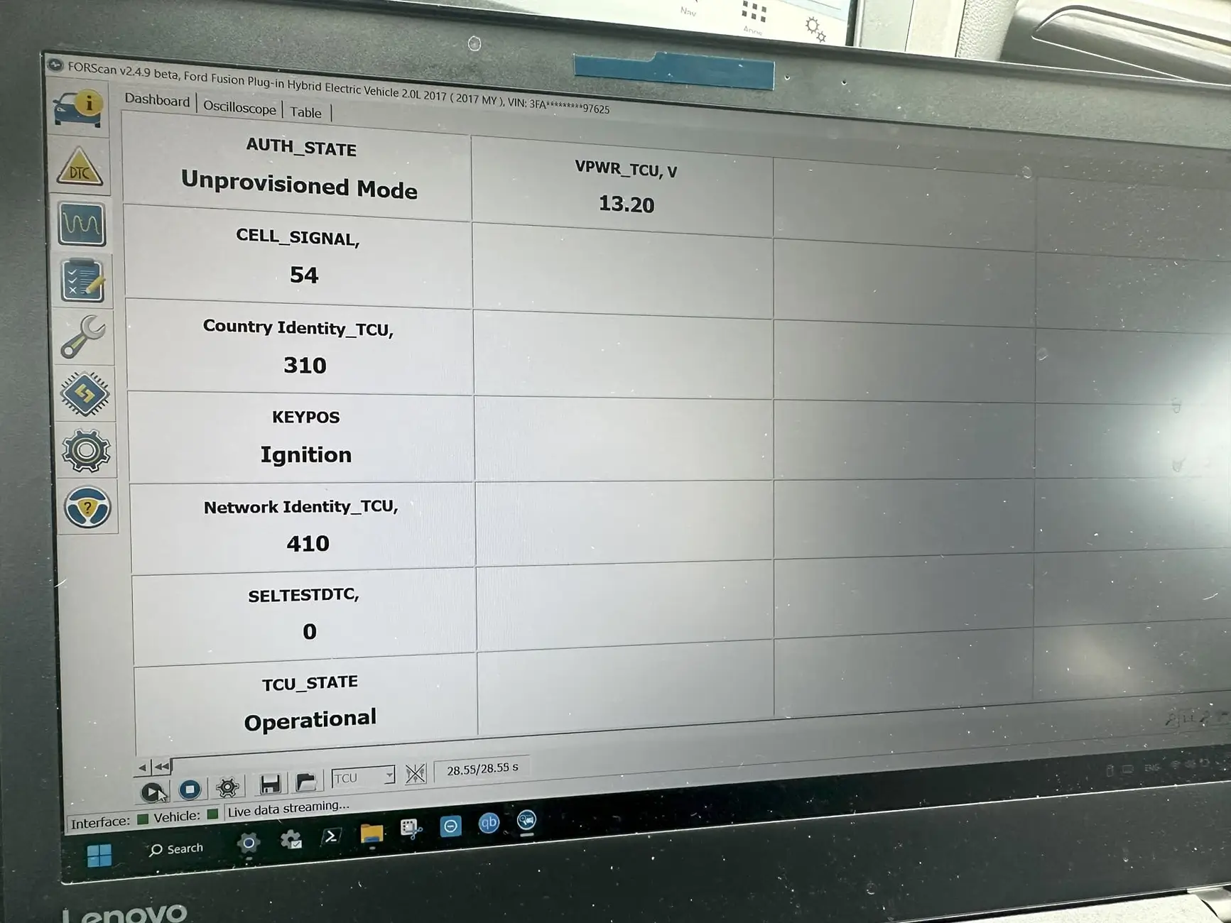
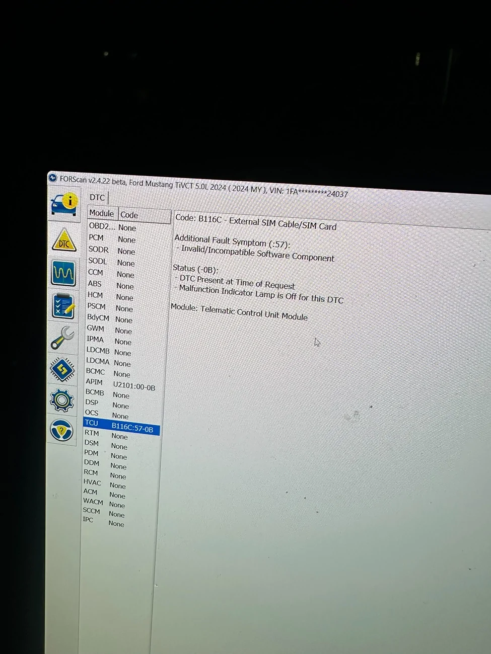
I'm trying to convert my TCU from North America to Europe on my Mustang. On the F150 I've read a topic of other people who have don this on their truck. See link below
https://www.f150lightningforum.com/...ontinent-region-change-usa-to-eu.34231/page-4
I saw these pictures what they posted, but since I'm not that good in reading pictures, I just need some help to understand before I bring my TCU to a local Phone Shop to fix it.
So what the person described was:
- Buy a Sim card adapter (bought)
- Remove the E-sim
- Solder the adapter to the TCU
He also said that he made a diagram, but I don't understand nothing from thst diagram. Maybe it's better to create an account on that forum and ask the person instead of opening a thread here, but since this is a Mustang, and since other owners maybe also want to do this, I wanted to share it here as well.
Are there any people here who do understand the pictures? My questions are:
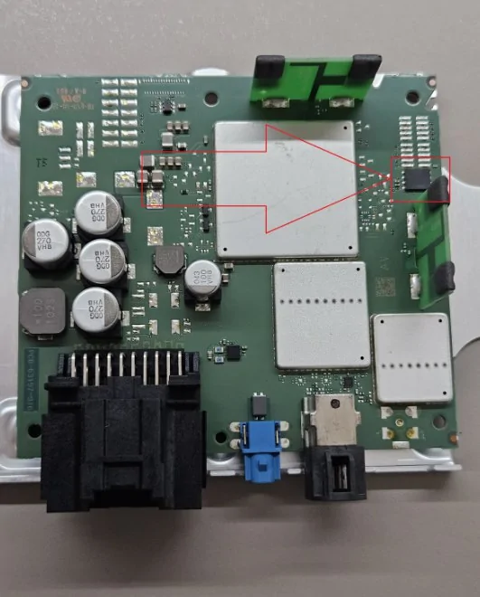
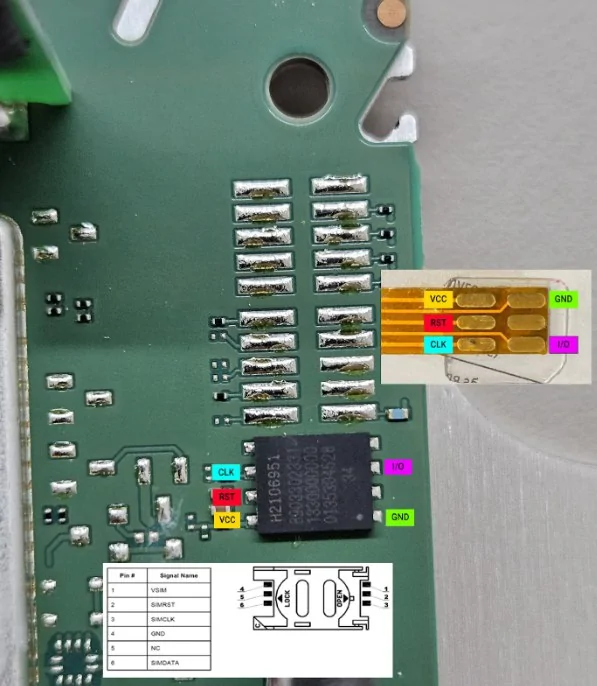
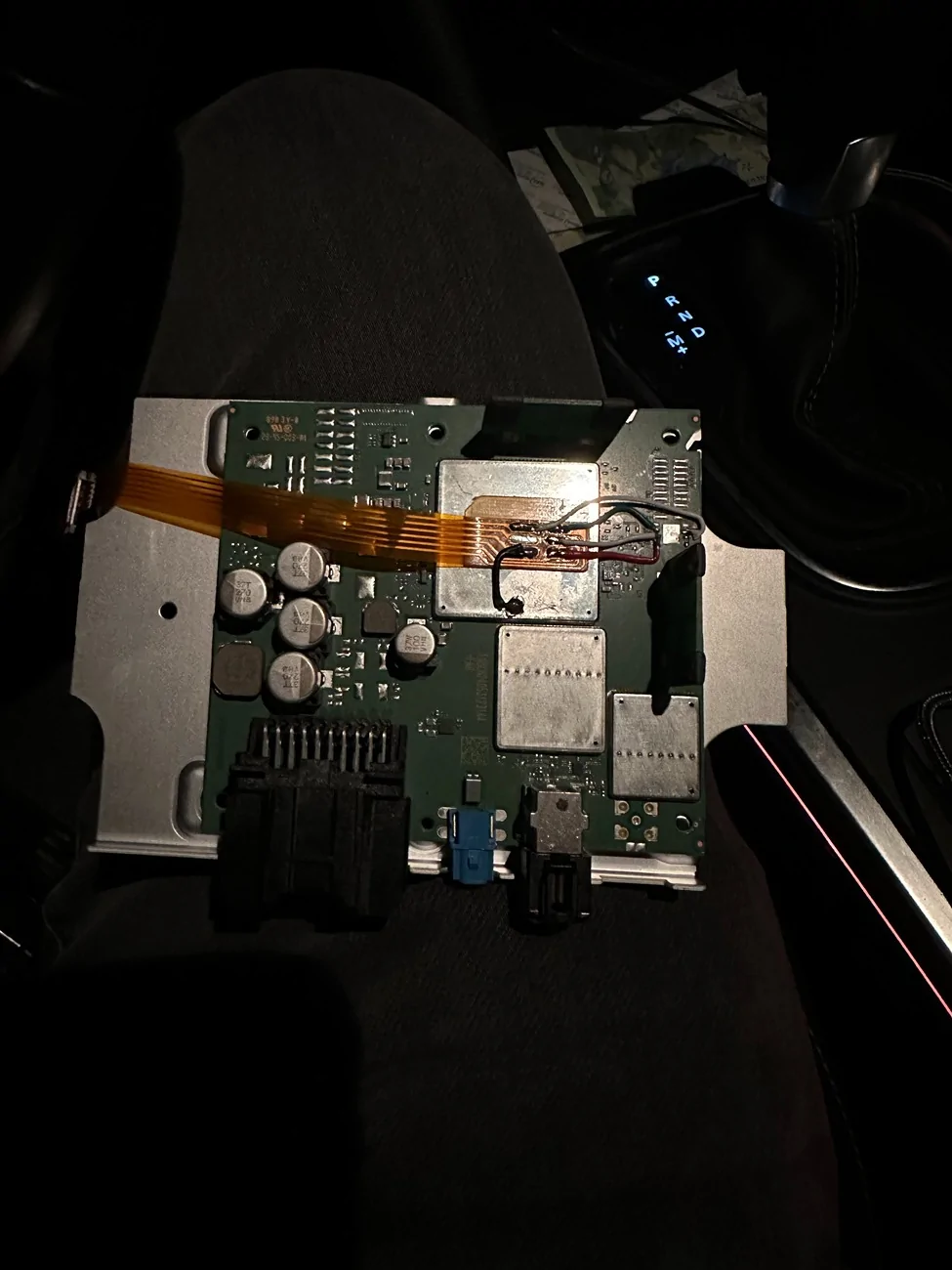
1. Is the first picture how the TCU looks like before modification?
2. Can you explain the diagram that is shown on the second picture?
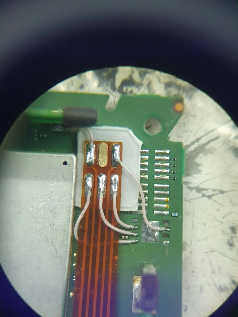
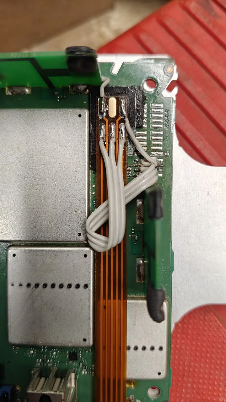
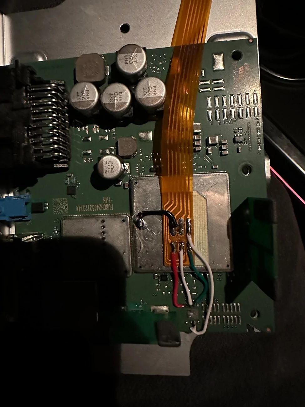
3. On the third picture it looks like the black plastic square thing is removed. I guess that is the E-sim? Now I can see 4 pins that are used and directed with white cables to somewhere else? Where exactly?
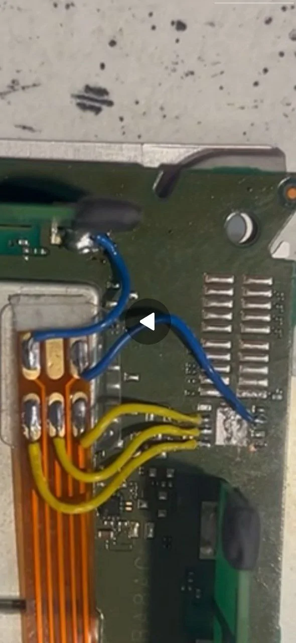
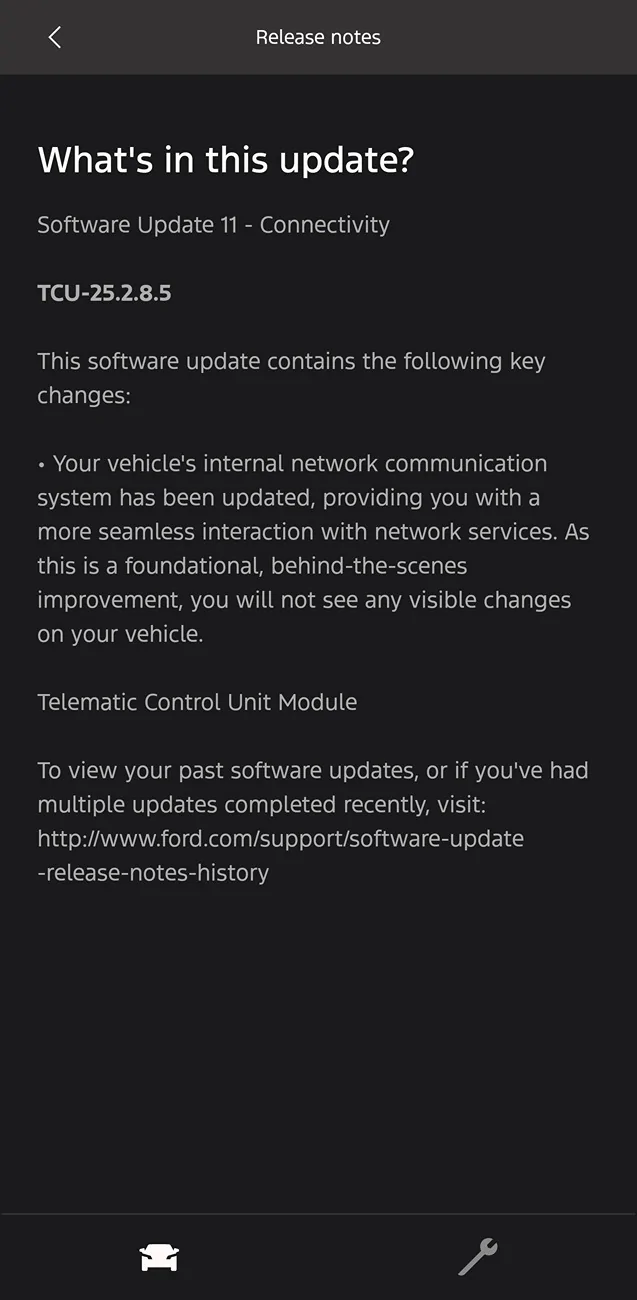
4. Picture 4 looks like a mess to me. What information can we get from this picture?
Thanks in advance.


https://www.f150lightningforum.com/...ontinent-region-change-usa-to-eu.34231/page-4
I saw these pictures what they posted, but since I'm not that good in reading pictures, I just need some help to understand before I bring my TCU to a local Phone Shop to fix it.
So what the person described was:
- Buy a Sim card adapter (bought)
- Remove the E-sim
- Solder the adapter to the TCU
He also said that he made a diagram, but I don't understand nothing from thst diagram. Maybe it's better to create an account on that forum and ask the person instead of opening a thread here, but since this is a Mustang, and since other owners maybe also want to do this, I wanted to share it here as well.
Are there any people here who do understand the pictures? My questions are:
1. Is the first picture how the TCU looks like before modification?
2. Can you explain the diagram that is shown on the second picture?
3. On the third picture it looks like the black plastic square thing is removed. I guess that is the E-sim? Now I can see 4 pins that are used and directed with white cables to somewhere else? Where exactly?
4. Picture 4 looks like a mess to me. What information can we get from this picture?
Thanks in advance.
Sponsored
")